toad.social is one of the many independent Mastodon servers you can use to participate in the fediverse.
Mastodon server operated by David Troy, a tech pioneer and investigative journalist addressing threats to democracy. Thoughtful participation and discussion welcome.

Administered by:

Server stats:

273
active users

#arduinouno

0 posts0 participants0 posts today
IT News<p>2025 One Hertz Challenge: Digital Clock Built With Analog Timer - You can use a microcontroller to build a clock. After all, a clock is just somethi... - <a href="https://hackaday.com/2025/08/13/2025-one-hertz-challenge-digital-clock-built-with-analog-timer/" rel="nofollow noopener" translate="no" target="_blank"><span class="invisible">https://</span><span class="ellipsis">hackaday.com/2025/08/13/2025-o</span><span class="invisible">ne-hertz-challenge-digital-clock-built-with-analog-timer/</span></a> <a href="https://schleuss.online/tags/clockhacks" class="mention hashtag" rel="nofollow noopener" target="_blank">#<span>clockhacks</span></a> <a href="https://schleuss.online/tags/arduinouno" class="mention hashtag" rel="nofollow noopener" target="_blank">#<span>arduinouno</span></a> <a href="https://schleuss.online/tags/555timer" class="mention hashtag" rel="nofollow noopener" target="_blank">#<span>555timer</span></a> <a href="https://schleuss.online/tags/clock" class="mention hashtag" rel="nofollow noopener" target="_blank">#<span>clock</span></a></p>
Blort™ 🐀Ⓥ🥋☣️<p>QUICK PAID OPPORTUNITY HELPING ANSWER A BASIC ARDUINO QUESTION</p><p>My friend is desperately trying to finish making their kids birthday present based on an Arduino project found online.</p><p>They're offering $20 USD per 10 minutes ($120/hr!) for someone to get on a quick Jitsi call with them asap and just tell them what wire needs to be attached where.</p><p>They're basically on step 2 of building this:<br><a href="https://www.instructables.com/Rat-Operated-Vehicle/" rel="nofollow noopener" translate="no" target="_blank"><span class="invisible">https://www.</span><span class="ellipsis">instructables.com/Rat-Operated</span><span class="invisible">-Vehicle/</span></a></p><p>...inspired by <span class="h-card" translate="no"><a href="https://io.mwl.io/@mwl" class="u-url mention" rel="nofollow noopener" target="_blank">@<span>mwl</span></a></span> 's <a href="https://ratoperatedvehicle.com" rel="nofollow noopener" translate="no" target="_blank"><span class="invisible">https://</span><span class="">ratoperatedvehicle.com</span><span class="invisible"></span></a>.</p><p>It's using an Arduino Uno compatible board (from an Elegoo Robot Car v4).</p><p>Please DM me so I can put you in touch, or forward / boost to help reach someone who can help. :)</p><p><a href="https://social.tchncs.de/tags/Arduino" class="mention hashtag" rel="nofollow noopener" target="_blank">#<span>Arduino</span></a> <a href="https://social.tchncs.de/tags/Maker" class="mention hashtag" rel="nofollow noopener" target="_blank">#<span>Maker</span></a> <a href="https://social.tchncs.de/tags/RatCar" class="mention hashtag" rel="nofollow noopener" target="_blank">#<span>RatCar</span></a> <a href="https://social.tchncs.de/tags/PetRats" class="mention hashtag" rel="nofollow noopener" target="_blank">#<span>PetRats</span></a> <a href="https://social.tchncs.de/tags/Electronics" class="mention hashtag" rel="nofollow noopener" target="_blank">#<span>Electronics</span></a> <a href="https://social.tchncs.de/tags/Elegoo" class="mention hashtag" rel="nofollow noopener" target="_blank">#<span>Elegoo</span></a> <a href="https://social.tchncs.de/tags/ArduinoUno" class="mention hashtag" rel="nofollow noopener" target="_blank">#<span>ArduinoUno</span></a> <a href="https://social.tchncs.de/tags/FOSS" class="mention hashtag" rel="nofollow noopener" target="_blank">#<span>FOSS</span></a> <a href="https://social.tchncs.de/tags/BoostOK" class="mention hashtag" rel="nofollow noopener" target="_blank">#<span>BoostOK</span></a></p>
Simple DIY Electronic Music Projects<p><strong>Using a Cheap 5V MIDI Interface at&nbsp;3V3</strong></p><p>I had a query about using one of the common Arduino MIDI Shields with an ESP32 and when I looked into it, this is where I got to.</p><p><em><strong>Warning!</strong> I strongly recommend using old or second hand equipment for your experiments.&nbsp; I am not responsible for any damage to expensive instruments!</em></p><p>If you are new to Arduino, see the&nbsp;<a href="https://diyelectromusic.wordpress.com/getting-started/" rel="nofollow noopener" target="_blank">Getting Started</a> pages.</p><p><strong>Parts list</strong></p><ul><li>Arduino Uno MIDI Shield</li><li>ESP32 or other 3V3 microcontroller</li><li>1x 22KΩ, 1x 33KΩ resistors for MIDI IN</li><li>1x 10Ω, 1×30Ω resistors for MIDI OUT</li><li>Breadboard and jumper wires</li></ul><p><strong>Arduino MIDI Shield</strong></p><p>These shields are available very cheaply and designed to plug directly onto an Arduino Uno. They are a variation of an original Olimex open source design (<a href="https://www.olimex.com/Products/Duino/Shields/SHIELD-MIDI/open-source-hardware" rel="nofollow noopener" target="_blank">details here</a>) but details of the specifics of this shield seem pretty sparse. But it isn’t too complex to figure out.</p><p>Essentially it is a 6N139-based 5V MIDI IN circuit and a non-buffered 5V MIDI OUT and THRU. The boards include a switch to cut off RX from MIDI to allow for sketch uploading. There is often a footprint for a button for RESET which may or may not be populated, and there is a block of breakout connectors for all the Arduino’s IO pins.</p><p>I did eventually happen upon an uncredited schematic in a random online cloud service file storage, so I’ve copied it over here.</p><p>And mapping this over to the board itself I found this PCB diagram. Note this has a URL for “soliddigi” on it, but that doesn’t seem to exist (or do anything) that I could see.</p><p>But whilst on the topic of this board, we can map out the IO pin breakouts for future reference too by simply examining the underside of the board:</p><p>From this we can see the following pinouts for the board.</p><p>Anyway, back to MIDI…</p><p><strong>Converting MIDI IN</strong></p><p>The output (to the Arduino) from the MIDI IN circuit of this board is a UART RX connection pulled high to 5V. The easiest way to drop that to 3V3 for use with a 3V3 logic system is to use a resistor divider as shown below.</p><p>The MIDI shield will still need to be powered by 5V but the output from the RX pin will now be dropped by the ratio 33K/(22K+33K) which is approximately 0.6. So 5V x 0.6 = 3V.</p><p>The choice of resistor for this specific application is relatively arbitrary as it is the ratio that is important, but it should be remembered that this is connecting both the optoisolator’s output (RX) and the microcontrollers IO pin (GP19 above) to GND so there will be limits on the amount of current that can be sourced from the two IO pins and that can be sunk into GND.</p><p><strong>Converting MIDI OUT</strong></p><p>Converting MIDI OUT isn’t quite so easy unfortunately. If the MIDI interface had included a buffer, like the 74HCT14 I’ve used in the past, then no conversion would be necessary – a 3V3 logic signal can drive that directly and the output would be a 5V signal to the rest of the MIDI circuit.</p><p>But it doesn’t – it is a directly connected 5V-expecting MIDI OUT circuit involving two 220Ω resistors. If this is driven from a 3V3 level then it is unlikely that there would be enough current to drive the optoisolator at the other end of the MIDI link.</p><p>The basic calculation goes as follows (see my <a href="https://diyelectromusic.com/2021/05/29/midi-connections-cheat-sheet/" rel="nofollow noopener" target="_blank">MIDI Connections Cheat&nbsp;Sheet</a> for details of the circuits) – this assumes one 220Ω resistor on the receiving side and two on the sending side as per the MIDI spec, and a typical 1.7V drop across the optoisolator.</p><p>For 5V operation, from Ohm’s law: Current = (5 – 1.7) / (220+220+200) = 5mA</p><p>For 3V3 operation: Current = (3.3 – 1.7) / (220+220+200) = 2mA</p><p>This is why the MIDI spec recommends 10Ω and 30Ω resistors for a 3V3 logic OUT circuit:</p><p>For proper 3V3 operation: Current = (3.3 – 1.7) / (220+30+10) = 6mA</p><p>Really, the easiest method, assuming the MIDI connectors/hardware are required to be used “as is” would be to include a 74HCT14 (the HCT variant, not the HC version) as a buffer by passing the 3V3 signal through two of the inverters.</p><p>But at this point, as this is just a couple of resistors, I’d probably look to remove the two 220Ω resistors in the OUTPUT circuit and attempt to patch in a 10Ω and 30Ω instead with the 30Ω pulling up to 3V3 rather than 5V.</p><p><strong>Patching the Shield</strong></p><p>Given all the above, I believe it is possible to patch this shield to support 3V3 logic operation by performing the following:</p><ul><li>Remove R3 and R4.</li><li>Cut the track to the RX Pin.</li><li>Add 10Ω between MIDI OUT R3 connector and TX.</li><li>Add 33Ω between MIDI OUT R4 connector and 3V3.</li><li>Add 22KΩ between RX and the centre pin of the ON/OFF switch (check this with a meter though – it was the middle pin for me!).</li><li>Add 33KΩ between RX and GND.</li></ul><p><strong>WARNING: <em>All of this is theoretical. I’ve not actually done it myself.</em></strong></p><p>Step 1: Remove R3, R4, cut RX track.</p><p>Step 2: Add resistors.</p><p>Note: I don’t believe that anything has to be done to the THRU as it is taken directly off the RX side of the 6N139, so that will continue to work (as I understand things) off the 5V circuit directly.</p><p><strong>Closing Thoughts</strong></p><p>Given the number of off-the-shelf 3V3 MIDI boards now available, I suspect in most cases acquiring one directly would be the better option to the above.</p><p>But having said that, these boards are available so cheaply and widely that it is worth considering. Also, there are 3V3 logic level boards in Uno form factor, so having a 3V3 version of the shield would be useful in any case.</p><p>But I repeat, other than testing the resistor divider on RX, I’ve not tested any of the modifications to the board itself. Do let me know if you’re brave enough to give it a go 🙂</p><p>At some point I might make my own 3V3 Uno format shield PCB…</p><p>Kevin</p><p></p><p><a rel="nofollow noopener" class="hashtag u-tag u-category" href="https://diyelectromusic.com/tag/arduino-uno/" target="_blank">#arduinoUno</a> <a rel="nofollow noopener" class="hashtag u-tag u-category" href="https://diyelectromusic.com/tag/esp32/" target="_blank">#esp32</a> <a rel="nofollow noopener" class="hashtag u-tag u-category" href="https://diyelectromusic.com/tag/midi/" target="_blank">#midi</a> <a rel="nofollow noopener" class="hashtag u-tag u-category" href="https://diyelectromusic.com/tag/midi-shield/" target="_blank">#midiShield</a></p>
IT News<p>Building a 3D-Printed Strandbeest - The Strandbeest is a walking machine, a creation of the celebrated artist Theo Jan... - <a href="https://hackaday.com/2025/01/16/building-a-3d-printed-strandbeest/" rel="nofollow noopener" translate="no" target="_blank"><span class="invisible">https://</span><span class="ellipsis">hackaday.com/2025/01/16/buildi</span><span class="invisible">ng-a-3d-printed-strandbeest/</span></a> <a href="https://schleuss.online/tags/3dprinterhacks" class="mention hashtag" rel="nofollow noopener" target="_blank">#<span>3dprinterhacks</span></a> <a href="https://schleuss.online/tags/arduinohacks" class="mention hashtag" rel="nofollow noopener" target="_blank">#<span>arduinohacks</span></a> <a href="https://schleuss.online/tags/strandbeest" class="mention hashtag" rel="nofollow noopener" target="_blank">#<span>strandbeest</span></a> <a href="https://schleuss.online/tags/arduinouno" class="mention hashtag" rel="nofollow noopener" target="_blank">#<span>arduinouno</span></a> <a href="https://schleuss.online/tags/3dprinted" class="mention hashtag" rel="nofollow noopener" target="_blank">#<span>3dprinted</span></a> <a href="https://schleuss.online/tags/robot" class="mention hashtag" rel="nofollow noopener" target="_blank">#<span>robot</span></a></p>
Pyrzout :vm:<p>All Aboard the Hack Train: Nottingham’s LED Revival <a href="https://hackaday.com/2025/01/04/all-aboard-the-hack-train-nottinghams-led-revival/" rel="nofollow noopener" translate="no" target="_blank"><span class="invisible">https://</span><span class="ellipsis">hackaday.com/2025/01/04/all-ab</span><span class="invisible">oard-the-hack-train-nottinghams-led-revival/</span></a> <a href="https://social.skynetcloud.site/tags/nottinghamhackspace" class="mention hashtag" rel="nofollow noopener" target="_blank">#<span>nottinghamhackspace</span></a> <a href="https://social.skynetcloud.site/tags/ReverseEngineering" class="mention hashtag" rel="nofollow noopener" target="_blank">#<span>ReverseEngineering</span></a> <a href="https://social.skynetcloud.site/tags/departureboard" class="mention hashtag" rel="nofollow noopener" target="_blank">#<span>departureboard</span></a> <a href="https://social.skynetcloud.site/tags/SoftwareHacks" class="mention hashtag" rel="nofollow noopener" target="_blank">#<span>SoftwareHacks</span></a> <a href="https://social.skynetcloud.site/tags/ArduinoHacks" class="mention hashtag" rel="nofollow noopener" target="_blank">#<span>ArduinoHacks</span></a> <a href="https://social.skynetcloud.site/tags/Hackerspaces" class="mention hashtag" rel="nofollow noopener" target="_blank">#<span>Hackerspaces</span></a> <a href="https://social.skynetcloud.site/tags/ArduinoUno" class="mention hashtag" rel="nofollow noopener" target="_blank">#<span>ArduinoUno</span></a> <a href="https://social.skynetcloud.site/tags/Nottingham" class="mention hashtag" rel="nofollow noopener" target="_blank">#<span>Nottingham</span></a> <a href="https://social.skynetcloud.site/tags/LEDHacks" class="mention hashtag" rel="nofollow noopener" target="_blank">#<span>LEDHacks</span></a> <a href="https://social.skynetcloud.site/tags/Discord" class="mention hashtag" rel="nofollow noopener" target="_blank">#<span>Discord</span></a> <a href="https://social.skynetcloud.site/tags/railway" class="mention hashtag" rel="nofollow noopener" target="_blank">#<span>railway</span></a> <a href="https://social.skynetcloud.site/tags/News" class="mention hashtag" rel="nofollow noopener" target="_blank">#<span>News</span></a> <a href="https://social.skynetcloud.site/tags/mqtt" class="mention hashtag" rel="nofollow noopener" target="_blank">#<span>mqtt</span></a> <a href="https://social.skynetcloud.site/tags/led" class="mention hashtag" rel="nofollow noopener" target="_blank">#<span>led</span></a></p>
IT News<p>All Aboard the Hack Train: Nottingham’s LED Revival - Hackerspaces are no strangers to repurposing outdated tech, and Nottingham Hackspa... - <a href="https://hackaday.com/2025/01/04/all-aboard-the-hack-train-nottinghams-led-revival/" rel="nofollow noopener" translate="no" target="_blank"><span class="invisible">https://</span><span class="ellipsis">hackaday.com/2025/01/04/all-ab</span><span class="invisible">oard-the-hack-train-nottinghams-led-revival/</span></a> <a href="https://schleuss.online/tags/nottinghamhackspace" class="mention hashtag" rel="nofollow noopener" target="_blank">#<span>nottinghamhackspace</span></a> <a href="https://schleuss.online/tags/reverseengineering" class="mention hashtag" rel="nofollow noopener" target="_blank">#<span>reverseengineering</span></a> <a href="https://schleuss.online/tags/departureboard" class="mention hashtag" rel="nofollow noopener" target="_blank">#<span>departureboard</span></a> <a href="https://schleuss.online/tags/softwarehacks" class="mention hashtag" rel="nofollow noopener" target="_blank">#<span>softwarehacks</span></a> <a href="https://schleuss.online/tags/arduinohacks" class="mention hashtag" rel="nofollow noopener" target="_blank">#<span>arduinohacks</span></a> <a href="https://schleuss.online/tags/hackerspaces" class="mention hashtag" rel="nofollow noopener" target="_blank">#<span>hackerspaces</span></a> <a href="https://schleuss.online/tags/arduinouno" class="mention hashtag" rel="nofollow noopener" target="_blank">#<span>arduinouno</span></a> <a href="https://schleuss.online/tags/nottingham" class="mention hashtag" rel="nofollow noopener" target="_blank">#<span>nottingham</span></a> <a href="https://schleuss.online/tags/ledhacks" class="mention hashtag" rel="nofollow noopener" target="_blank">#<span>ledhacks</span></a> <a href="https://schleuss.online/tags/discord" class="mention hashtag" rel="nofollow noopener" target="_blank">#<span>discord</span></a> <a href="https://schleuss.online/tags/railway" class="mention hashtag" rel="nofollow noopener" target="_blank">#<span>railway</span></a> <a href="https://schleuss.online/tags/news" class="mention hashtag" rel="nofollow noopener" target="_blank">#<span>news</span></a> <a href="https://schleuss.online/tags/mqtt" class="mention hashtag" rel="nofollow noopener" target="_blank">#<span>mqtt</span></a> <a href="https://schleuss.online/tags/led" class="mention hashtag" rel="nofollow noopener" target="_blank">#<span>led</span></a></p>
IT News<p>Crafting a Cardboard Tribute to Puzzle Bobble - What do you get when you cross cardboard, deodorant rollers, and a love for retro ... - <a href="https://hackaday.com/2025/01/02/crafting-a-cardboard-tribute-to-puzzle-bobble/" rel="nofollow noopener" translate="no" target="_blank"><span class="invisible">https://</span><span class="ellipsis">hackaday.com/2025/01/02/crafti</span><span class="invisible">ng-a-cardboard-tribute-to-puzzle-bobble/</span></a> <a href="https://schleuss.online/tags/retrocomputing" class="mention hashtag" rel="nofollow noopener" target="_blank">#<span>retrocomputing</span></a> <a href="https://schleuss.online/tags/arduinohacks" class="mention hashtag" rel="nofollow noopener" target="_blank">#<span>arduinohacks</span></a> <a href="https://schleuss.online/tags/puzzlebobble" class="mention hashtag" rel="nofollow noopener" target="_blank">#<span>puzzlebobble</span></a> <a href="https://schleuss.online/tags/puzzlebobble" class="mention hashtag" rel="nofollow noopener" target="_blank">#<span>puzzlebobble</span></a> <a href="https://schleuss.online/tags/bust" class="mention hashtag" rel="nofollow noopener" target="_blank">#<span>bust</span></a>-a-move <a href="https://schleuss.online/tags/retrogaming" class="mention hashtag" rel="nofollow noopener" target="_blank">#<span>retrogaming</span></a> <a href="https://schleuss.online/tags/arduinouno" class="mention hashtag" rel="nofollow noopener" target="_blank">#<span>arduinouno</span></a> <a href="https://schleuss.online/tags/toyhacks" class="mention hashtag" rel="nofollow noopener" target="_blank">#<span>toyhacks</span></a> <a href="https://schleuss.online/tags/arduino" class="mention hashtag" rel="nofollow noopener" target="_blank">#<span>arduino</span></a> <a href="https://schleuss.online/tags/games" class="mention hashtag" rel="nofollow noopener" target="_blank">#<span>games</span></a> <a href="https://schleuss.online/tags/mame" class="mention hashtag" rel="nofollow noopener" target="_blank">#<span>mame</span></a> <a href="https://schleuss.online/tags/lua" class="mention hashtag" rel="nofollow noopener" target="_blank">#<span>lua</span></a></p>
Pyrzout :vm:<p>A Parts Bin MIDI Controller in 24 Hours <a href="https://hackaday.com/2024/10/20/a-parts-bin-midi-controller-in-24-hours/" rel="nofollow noopener" translate="no" target="_blank"><span class="invisible">https://</span><span class="ellipsis">hackaday.com/2024/10/20/a-part</span><span class="invisible">s-bin-midi-controller-in-24-hours/</span></a> <a href="https://social.skynetcloud.site/tags/emergencystop" class="mention hashtag" rel="nofollow noopener" target="_blank">#<span>emergencystop</span></a> <a href="https://social.skynetcloud.site/tags/MusicalHacks" class="mention hashtag" rel="nofollow noopener" target="_blank">#<span>MusicalHacks</span></a> <a href="https://social.skynetcloud.site/tags/arcadebutton" class="mention hashtag" rel="nofollow noopener" target="_blank">#<span>arcadebutton</span></a> <a href="https://social.skynetcloud.site/tags/drummachine" class="mention hashtag" rel="nofollow noopener" target="_blank">#<span>drummachine</span></a> <a href="https://social.skynetcloud.site/tags/pelicancase" class="mention hashtag" rel="nofollow noopener" target="_blank">#<span>pelicancase</span></a> <a href="https://social.skynetcloud.site/tags/ArduinoUno" class="mention hashtag" rel="nofollow noopener" target="_blank">#<span>ArduinoUno</span></a> <a href="https://social.skynetcloud.site/tags/arduino" class="mention hashtag" rel="nofollow noopener" target="_blank">#<span>arduino</span></a> <a href="https://social.skynetcloud.site/tags/drumkit" class="mention hashtag" rel="nofollow noopener" target="_blank">#<span>drumkit</span></a> <a href="https://social.skynetcloud.site/tags/music" class="mention hashtag" rel="nofollow noopener" target="_blank">#<span>music</span></a> <a href="https://social.skynetcloud.site/tags/midi" class="mention hashtag" rel="nofollow noopener" target="_blank">#<span>midi</span></a></p>
IT News<p>A Parts Bin MIDI Controller in 24 Hours - Part of the reason MIDI has hung on as a standard in the musical world for so long... - <a href="https://hackaday.com/2024/10/20/a-parts-bin-midi-controller-in-24-hours/" rel="nofollow noopener" translate="no" target="_blank"><span class="invisible">https://</span><span class="ellipsis">hackaday.com/2024/10/20/a-part</span><span class="invisible">s-bin-midi-controller-in-24-hours/</span></a> <a href="https://schleuss.online/tags/emergencystop" class="mention hashtag" rel="nofollow noopener" target="_blank">#<span>emergencystop</span></a> <a href="https://schleuss.online/tags/musicalhacks" class="mention hashtag" rel="nofollow noopener" target="_blank">#<span>musicalhacks</span></a> <a href="https://schleuss.online/tags/arcadebutton" class="mention hashtag" rel="nofollow noopener" target="_blank">#<span>arcadebutton</span></a> <a href="https://schleuss.online/tags/drummachine" class="mention hashtag" rel="nofollow noopener" target="_blank">#<span>drummachine</span></a> <a href="https://schleuss.online/tags/pelicancase" class="mention hashtag" rel="nofollow noopener" target="_blank">#<span>pelicancase</span></a> <a href="https://schleuss.online/tags/arduinouno" class="mention hashtag" rel="nofollow noopener" target="_blank">#<span>arduinouno</span></a> <a href="https://schleuss.online/tags/arduino" class="mention hashtag" rel="nofollow noopener" target="_blank">#<span>arduino</span></a> <a href="https://schleuss.online/tags/drumkit" class="mention hashtag" rel="nofollow noopener" target="_blank">#<span>drumkit</span></a> <a href="https://schleuss.online/tags/music" class="mention hashtag" rel="nofollow noopener" target="_blank">#<span>music</span></a> <a href="https://schleuss.online/tags/midi" class="mention hashtag" rel="nofollow noopener" target="_blank">#<span>midi</span></a></p>
Simple DIY Electronic Music Projects<p>I covered all the theory and main functions of the code for my <a href="https://diyelectromusic.com/2024/10/04/arduino-euclidean-gate-sequencer/" rel="nofollow noopener" target="_blank">Arduino Euclidean Gate&nbsp;Sequencer</a> in my previous post. In this one I look a little more at some hardware that hopefully lets me use this to actually control something useful!</p><p><em><strong>Warning!</strong> I strongly recommend using old or second hand equipment for your experiments.&nbsp; I am not responsible for any damage to expensive instruments!</em></p><p>All of the key ideas along with a list of references for the main concepts used in this project were listed in my first post here: <a href="https://diyelectromusic.com/2024/10/04/arduino-euclidean-gate-sequencer/" rel="nofollow noopener" target="_blank">Arduino Euclidean Gate&nbsp;Sequencer</a>.</p><p>If you are new to Arduino, see the&nbsp;<a href="https://diyelectromusic.wordpress.com/getting-started/" rel="nofollow noopener" target="_blank">Getting Started</a> pages.</p><p><strong>Experiment 1: Arduino to Arduino to MIDI</strong></p><p>I could add MIDI functionality to my Euclidean clock generator, but instead opted to build a TRIGGER to MIDI converter using a second Arduino. This has several digital inputs setup to receive TRIGGER pulses and on reception will send out a preconfigured MIDI message.</p><p>The configuration is such that a NoteOn is sent for a specific drum on MIDI channel 10 which is typically used for percussion. Which drum corresponds to which input is configurable in the code.</p><p>Full details of this so far can be found here: <a href="https://diyelectromusic.com/2024/10/06/arduino-drum-trigger-to-midi/" rel="nofollow noopener" target="_blank">Arduino Drum Trigger to&nbsp;MIDI</a>. This is how I connected them up and it seems to work pretty well.</p><p><strong>Arduino to GATE or TRIGGER Output</strong></p><p>Here I’m setting up the board to be able to drive an external device.</p><p><em>As always, the standard warning applies – use second hand or disposable equipment for experiments. <strong>I am not responsible for damage to expensive instruments.</strong> Assess what I’m doing, decide for yourself how it will affect your equipment and then use at your own risk.</em></p><p>I’ve followed the design from HAGIWO’s GATE sequencer, which is detailed in full here: <a href="https://note.com/solder_state/n/n17c69afd484d" rel="nofollow noopener" target="_blank">https://note.com/solder_state/n/n17c69afd484d</a></p><p>This recommends the following:</p><ul><li>All outputs clamped to the Arduino’s 5V and GND using BAT43 Schotky diodes.</li><li>470Ω resistor on the output to set an output impedance.</li></ul><p>I’m wanting to plug this into my Korg Volca Sync In.</p><p>With an oscilloscope I examined the Sync Out signal and confirmed that it is a 5V pulse of 15mS. As I’m only plugging a 5V Arduino into the 5V accepting Korg, I’ve not bothered with the clamping diodes for my simple experiments, but if I build this up into a PCB then I’ll probably add them in to make it a little more universal.</p><p>The TRS jack is wired to be compatible with the Korg Volca Sync In port – i.e. using just the tip and shield. A stereo or mono 3.5mm jack to jack cable (as comes supplied with a Volca) can then be used to connect it up.</p><p>The blue jumper wire can be used to select which of the Euclidean clock outputs to use.</p><p>The code is built for TRIGGER mode, so each output is a single 10mS pulse. This is shorter than that produced by the Volcas but generally seems to work.</p><p>When first connected or when the tempo is changed I sometimes hear some spurious or irregular triggering, but once it has settled down it seems to work fine for my Volca Keys, Volca Modular, and Volca FM2.</p><p><strong>Arduino to ESP32 Synth Thing Baby8</strong></p><p>The <a href="https://diyelectromusic.com/2024/09/01/baby8-cv-step-sequencer-part-4-in-use/" rel="nofollow noopener" target="_blank">“Baby8” CV Step Sequencer</a> has an option to be driven by an external clock. If the INT_CLK jumper is removed then it will trigger off whatever is plugged into the CLK header pin (third down from the top of the header).</p><p>This means that, assuming the Baby8 is powered off 5V, then any of the Arduino GPIO clock outputs (D8-D13) can be directly connected as shown below.</p><p>This is directly connecting the Arduino’s GPIO OUTPUT pins (the clock) to the Baby 8’s 4017 timer CLK pin. As in general terms directly connecting an OUTPUT to an INPUT is deemed an ok thing to do (INPUTs are high impedance as I understand things), i.e. the output of a microcontroller, 555 timer, or NAND oscillator and so on are often set up to drive the CLK pin directly, then connecting it directly to an Arduino GPIO OUTPUT should be fine.</p><p>It is also possible to drive the actual <a href="https://diyelectromusic.com/2024/05/07/educational-diy-synth-thing/" rel="nofollow noopener" target="_blank">Educational DIY Synth&nbsp;Thing</a> itself as it includes 5V tolerant GATE and TRIGGER inputs, but having a regular clock pulse with no pitch CV information is somewhat limited.</p><p>But using the Baby8 as shown above with the Synth Thing too should work fine, although if the Baby 8 is powered off 5V then the top of the potentiometer’s range will be slightly too high for the Synth Thing which will top-out at around 3V3. It won’t damage the Synth Thing as the CV inputs are clamped to the 0 and 3V3 power rails.</p><p><strong>Closing Thoughts</strong></p><p>Naturally getting the logic signal doing the right thing on a GPIO port is only part of the equation. That is only useful if it is able to control something else.</p><p>This post looked at some options, from the hacky “quick and dirty” versions through to what ought to be done to do things properly.</p><p>I’m still chewing over the idea of some kind of trigger shield or similar PCB.</p><p>Kevin</p><p><a href="https://diyelectromusic.com/2024/10/07/arduino-euclidean-gate-sequencer-part-2/" class="" rel="nofollow noopener" target="_blank">https://diyelectromusic.com/2024/10/07/arduino-euclidean-gate-sequencer-part-2/</a></p><p><a rel="nofollow noopener" class="hashtag u-tag u-category" href="https://diyelectromusic.com/tag/arduino-uno/" target="_blank">#arduinoUno</a> <a rel="nofollow noopener" class="hashtag u-tag u-category" href="https://diyelectromusic.com/tag/baby8/" target="_blank">#baby8</a> <a rel="nofollow noopener" class="hashtag u-tag u-category" href="https://diyelectromusic.com/tag/euclidean/" target="_blank">#euclidean</a> <a rel="nofollow noopener" class="hashtag u-tag u-category" href="https://diyelectromusic.com/tag/gate/" target="_blank">#gate</a> <a rel="nofollow noopener" class="hashtag u-tag u-category" href="https://diyelectromusic.com/tag/midi/" target="_blank">#midi</a> <a rel="nofollow noopener" class="hashtag u-tag u-category" href="https://diyelectromusic.com/tag/step-sequence/" target="_blank">#stepSequence</a> <a rel="nofollow noopener" class="hashtag u-tag u-category" href="https://diyelectromusic.com/tag/synth-thing/" target="_blank">#synthThing</a></p>
Rommudoh<p><a href="https://social.tchncs.de/tags/soldering" class="mention hashtag" rel="nofollow noopener" target="_blank">#<span>soldering</span></a> project this weekend: <a href="https://social.tchncs.de/tags/Arduino" class="mention hashtag" rel="nofollow noopener" target="_blank">#<span>Arduino</span></a> Make Your Uno kit: <a href="https://makeyouruno.arduino.cc/" rel="nofollow noopener" translate="no" target="_blank"><span class="invisible">https://</span><span class="">makeyouruno.arduino.cc/</span><span class="invisible"></span></a><br>Today, I soldered the <a href="https://social.tchncs.de/tags/ArduinoUno" class="mention hashtag" rel="nofollow noopener" target="_blank">#<span>ArduinoUno</span></a> board. Next will be the synthesizer shield.<br>It was fun and everything is labeled on the silkscreen.<br><a href="https://social.tchncs.de/tags/solderingkit" class="mention hashtag" rel="nofollow noopener" target="_blank">#<span>solderingkit</span></a> <a href="https://social.tchncs.de/tags/electronics" class="mention hashtag" rel="nofollow noopener" target="_blank">#<span>electronics</span></a> <a href="https://social.tchncs.de/tags/atmega" class="mention hashtag" rel="nofollow noopener" target="_blank">#<span>atmega</span></a> <a href="https://social.tchncs.de/tags/usbc" class="mention hashtag" rel="nofollow noopener" target="_blank">#<span>usbc</span></a></p>
Continued thread

Well, I couldn't leave it alone...

The Arduino code now allows triangle waves, up to 1.0MHz (same as square waves), and sine waves up to 12.5MHz.

Also managed to push my Owon VDS1022i to its limits... the sine wave started to look a bit ropey after 5.0MHz, but not bad until then.

The design, updated code and even more pictures are all shared on GitHub too:

github.com/ilneill/DFG-ArdAD98

#FrequencyGenerator
#Arduino
#ArduinoUno
#ArduinoNano
#AD9833
#MCP41010
#RotaryEncoder
#KY040
#HD44780lcd

Continued thread

Hurrah! My latest project, an Arduino/AD9833 based digital frequency generator, is complete... And it works too 🎉

Impressed with rotary encoders and the AD9833 module. Very pleased with my Owon VDS1022i USB oscilloscope performance!

Design drawn, built. Done ✅
Code written, tested. Done ✅

The design, code and more pictures are all shared on GitHub too:

github.com/ilneill/DFG-ArdAD98

#FrequencyGenerator
#Arduino
#ArduinoUno
#ArduinoNano
#AD9833
#MCP41010
#RotaryEncoder
#KY-040
#HD44780lcd

TFW your final project is due in a month and you're sitting here about to change the control mechanisms. Again.

Think Imma bite the bullet and change it to a PLC (Likely Studio 500) and interface it with an arduino to control the steppers and display the timer.

It stinks considering how much time I've spent trying to get the pi up and running, then working, but getting LED matrices to work with it has burnt me out. Ultimately, I have more confidence in my PLC programming skills, and the arduino hopefully has enough documentation online to help me figure out some stepper motor controls.

One month. I got this.

Following my previous project... A rather disappointing analogue waveform generator, may I introduce you to my latest project - a digital waveform generator.

Working on the overall design, some Arduino code and a Fritzing drawing to accompany it.

This 3.3v/5v module has an AD9833 frequency generator, an MCP41010 digital potentiometer and an AD8051 opamp.

I really enjoy joining hardware and software to make a system.

#FrequencyGenerator
#Arduino
#ArduinoUno
#ArduinoNano
#AD9833
#MCP41010

Here are the build notes for my Arduino EEPROM Reader PCB Design.

Warning! I strongly recommend using old or second hand equipment for your experiments.  I am not responsible for any damage to expensive instruments!

If you are new to Arduino, see the Getting Started pages.

Bill of Materials

  • Arduino EEPROM Reader PCB (GitHub link below).
  • 2x 74HC595 shift registers.
  • 3x 100nF ceramic capacitors.
  • Pin headers and 3x jumpers.
  • 28-pin, wide, ZIF socket.
  • Optional: 2x 16-way DIP sockets.
  • Arduino headers.

Build Steps

This is the suggested order of assembly:

  • Important: Correct the errata in the PCB (see later).
  • DIP sockets (if used) or 595 devices (if not).
  • Disc capacitors.
  • 3-way jumper headers.
  • ZIF socket.
  • Arduino pin headers.

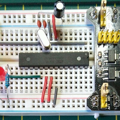
Here are some build photos.

Testing

I recommend performing the general tests described here: PCBs.

It is then worth temporarily tying the 8 data lines to 8 of the address lines via resistors so that the data read will be the same as the address on the chosen address lines. This would prove that everything is connected up sensibly.

It is also worth verifying the operation of OE (pin 22) and the state of VPP (HIGH) and CE (LOW).

In the photo, I’ve soldered up a simple test jig to tie D0-D7 to A0-A7 via resistors. I’m also using some “LED bytes” that have been doctored slightly to fit an Arduino, to indicate the status of the data lines which is pretty useful for seeing what is going on.

Then it would be useful to have a ROM for which the contents are known and then dump that entirely, for example to the Arduino serial console, to ensure that all data is being read correctly.

IMPORTANT: At this point in time, this board has not been tested for reading or writing to a 28Cxxx device. It has only been used for reading from a single 27C256 device.

PCB Errata

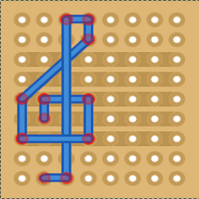
There is a problem with the trace that follows down the right-hand side of the board from D4 to the latch pin of the 595 (pin 12). It passes too close to one of the Arduino’s mounting holes and consequently is shorted to GND.

To fix it, it is possible to scrape off the track from around the hole and then use a patch wire. Having already built my board, this is the approach I took but if something conductive is used in the mounting hole in the future it may well short things out again.

It is probably better to cut the traces, prior to soldering any components, in the following places:

And then remake the connection with a patch wire which can be added as shown below:

My patched board:

Find it on GitHub here.

Sample Applications

With the correct jumper configuration, this PCB should be able to be used with Ben Eater’s Arduino EEPROM Programmer code – but this is untested.

The code I’ve used as part of my DX100 investigation (details to follow) to read out the contents of a 27C256 compatible device can be found here: https://github.com/diyelectromusic/sdemp/tree/main/src/Misc/Arduino_EPROM_Reader.

Closing Thoughts

I’m not sure what I managed to disable in the design rules checker to miss the fact that that trace was too close to the hole. Oh well. I’ll have to investigate the board constraints I’ve been using.

As already mentioned, while this should in theory support reading and writing of 28Cxxx devices, as described in Ben Eater’s Github, at present it has only been used with 27C256 devices and only for reading.

I’ll attempt to get hold of some approrpiate devices and give it a go at some point. Watch this space!

Kevin

https://diyelectromusic.wordpress.com/2024/01/28/arduino-eeprom-reader-pcb-build-guide/